Views: 265 Author: Dongguan PRES Publish Time: 2026-09-18 Origin: Site


Content Menu
● Why PEEK Shrinkage Matters for Connectors
● The Basic PEEK Shrinkage Calculation
>> Worked Example: Tight Connector Pin Cavity
● Typical PEEK Molding Shrinkage Ranges
● Flow Direction Changes Everything
>> Design Rule for Connector Engineers
● Material Selection: Unfilled vs. Reinforced PEEK
● Process Controls That Reduce Variation
>> 1. Dry the PEEK Resin Correctly
>> 2. Stabilize Melt and Mold Temperatures
>> 3. Optimize Packing Pressure and Holding Time
>> 4. Use Uniform Wall Thickness
● A Practical Validation Plan for High-Tolerance Connectors
>> Stage 1: Define Functional Dimensions
>> Stage 2: Measure at Defined Intervals
>> Stage 3: Confirm Process Capability
● Common PEEK Shrinkage Problems—and How to Solve Them
>> Problem: Connector Pitch Is Out of Tolerance
>> Problem: Circular Connector Shows Ovality
>> Problem: Metal Inserts Cause Cracking or Dimension Drift
>> Problem: Parts Pass at Molding but Fail Later
● Why OEM Customers Choose PRES
● Request a PEEK Connector Shrinkage Review
● FAQ
>> What is the typical PEEK molding shrinkage rate?
>> How do I calculate the PEEK mold cavity size?
>> Does glass-filled PEEK shrink less than unfilled PEEK?
>> Why does a PEEK connector change size after molding?
>> Can PEEK connectors achieve tight tolerances?
>> Is carbon-fiber-filled PEEK suitable for electrical connectors?
>> Should PEEK connector molds be steel-safe?
PEEK molding shrinkage is one of the most important variables in producing high-tolerance electrical, fluid-handling, sensor, and industrial connectors. At Dongguan PRES Group Co., Ltd., we help overseas brands, wholesalers, and manufacturers turn demanding PEEK connector designs into repeatable production parts through OEM material supply, mold-development support, and process-focused engineering.
For a connector, a fraction of a millimeter can decide whether a seal leaks, a pin loses retention, a latch fails to engage, or a mating component becomes too tight. PEEK offers exceptional heat resistance, chemical resistance, mechanical strength, and electrical insulation performance—but its semi-crystalline structure means shrinkage must be engineered, not guessed.
This guide explains how to calculate PEEK injection molding shrinkage, compensate tooling dimensions, control directional variation, and validate production parts for tight-tolerance connector programs.
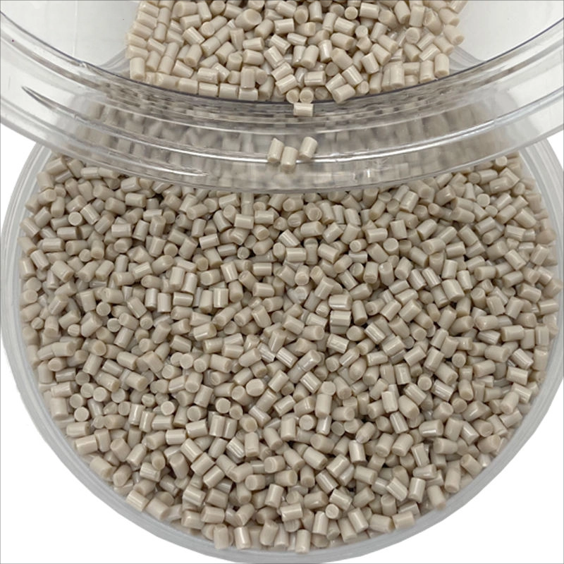
PEEK, or polyether ether ketone, is a semi-crystalline high-performance thermoplastic. During injection molding, molten PEEK enters the cavity at a high temperature, cools, crystallizes, and contracts. The resulting difference between mold-cavity dimensions and finished-part dimensions is known as molding shrinkage.
For general-purpose molded parts, a small dimensional change may be manageable. For high-tolerance connectors, it can create immediate functional problems:
- Terminal cavities become undersized, increasing insertion force or damaging metal contacts
- Pin-retention features become oversized or undersized, reducing mechanical security
- Sealing grooves shift, causing O-ring compression outside the specified range
- Latch arms warp, creating inconsistent mating and unmating forces
- Threaded or bayonet features misalign, compromising assembly performance
- Multi-cavity production becomes inconsistent, increasing sorting, scrap, and customer complaints
At PRES, we view PEEK molding shrinkage as a system-level issue. Resin grade, fiber loading, gate location, mold temperature, packing profile, wall thickness, cooling balance, and inspection timing all interact. A correct shrinkage estimate is necessary, but it is only the starting point for a robust connector program.
The standard relationship between mold size and final part size is straightforward:
Where shrinkage is expressed as a decimal.
For example, if a connector body requires a finished width of 20.00 mm and the expected PEEK molding shrinkage is 1.20%:
The starting cavity dimension should therefore be approximately 20.243 mm, before accounting for tolerance strategy, steel-safe conditions, polishing, texture, and tool-adjustment capability.
Assume a high-temperature PEEK connector requires a finished terminal-cavity dimension of 4.00 mm. The selected unfilled PEEK grade is expected to shrink 1.30% in the relevant direction.
The theoretical mold dimension is 4.053 mm.
However, connector engineering does not stop there. If the mating terminal requires a functional opening of 4.00 ± 0.03 mm, the mold design team should consider:
- The actual shrinkage behavior of the selected production grade
- Flow-direction versus cross-flow shrinkage
- Dimensional results after 24 hours, 48 hours, or a defined conditioning period
- Tool wear over the expected production volume
- Measurement-system capability
- The likely direction of future tool corrections
For this reason, steel-safe tooling is often the practical strategy. It gives the project team room to enlarge or reduce a critical feature after first-article trials, rather than locking the program into an irreversible cavity dimension.
There is no single universal PEEK shrinkage figure. The correct value must come from the technical data sheet for the exact resin grade and be verified through production trials.
Unfilled PEEK often shows approximately 1.0% to 1.8% molding shrinkage, while reinforced grades may show substantially lower shrinkage in the flow direction. Directional behavior can become more pronounced when glass or carbon fiber is added. Published examples for unfilled PEEK include values around 1.0% parallel to flow and 1.3% normal to flow, while 30% carbon-fiber-filled PEEK may show values near 0.1% along flow and 0.5% across flow under specified testing conditions. Actual parts can differ because geometry and process settings matter.
| PEEK material category | Typical molding shrinkage tendency | Connector design implication |
|---|---|---|
| Unfilled PEEK | Approximately 1.0%–1.8% | Higher overall shrinkage; careful cavity oversizing is essential |
| Glass-fiber-filled PEEK | Often lower in flow direction; more directional | Better stiffness, but flow orientation can affect flatness and alignment |
| Carbon-fiber-filled PEEK | Can be very low along flow; cross-flow remains higher | Excellent dimensional stability in selected directions, but anisotropy must be managed |
| Mineral- or specialty-filled PEEK | Grade-dependent | Confirm values using the specific supplier data sheet and molded-part trials |
Important: Datasheet shrinkage values are comparative processing data, not a guarantee of final part dimensions. They are usually measured on standardized test bars under stated molding conditions. A thin-wall connector with multiple terminal cavities, ribs, seals, and gates will not behave exactly like a standard test specimen. Victrex specifically notes that actual mold shrinkage depends strongly on part geometry, mold configuration, and processing conditions.
For precision connectors, the most common shrinkage mistake is treating PEEK as isotropic. It is not.
As PEEK flows through a mold, molecular orientation develops. In filled grades, glass or carbon fibers also align preferentially with flow. This produces different shrinkage values:
- Along flow: The direction in which polymer travels from the gate
- Across flow: The direction perpendicular to polymer flow
- Through thickness: Often influenced by cooling rate, packing, crystallization, and part-wall geometry
A connector may have a critical center-to-center pin pitch in one direction and a sealing land in another. If the gate orientation is poorly chosen, one critical dimension may be stable while another drifts outside specification.
Place gates and orient flow so the lowest and most predictable shrinkage direction supports the most critical dimension.
For example:
- For a connector with a critical row of terminal positions, gate placement should be evaluated relative to the terminal-pitch direction.
- For a circular connector, balanced filling is particularly important to avoid ovality.
- For a long connector housing, avoid a gate layout that creates unequal flow fronts and asymmetric fiber orientation.
- For sealing interfaces, use uniform wall thickness and balanced cooling to reduce local shrinkage gradients.
PRES recommends conducting mold-flow analysis before cutting steel when a PEEK connector includes narrow pin spacing, insert molding, thin walls, long flow lengths, or demanding flatness requirements.
The right PEEK grade depends on more than strength or heat resistance. For a high-tolerance connector, it must also support predictable shrinkage and stable post-molding dimensions.
| Selection factor | Unfilled PEEK | Glass-fiber-filled PEEK | Carbon-fiber-filled PEEK |
|---|---|---|---|
| Dimensional behavior | More uniform than fiber-filled grades, but higher total shrinkage | More anisotropic | Often strongest directional shrinkage difference |
| Electrical insulation | Excellent | Usually suitable, subject to application requirements | May be unsuitable where electrical insulation is essential |
| Stiffness | High | Higher | Very high |
| Surface finish | Generally smoother | Fiber texture may be visible | Fiber texture and conductive behavior may be concerns |
| Connector applications | Insulating housings, precision seal features, fluid connectors | Structural housings and mechanically loaded connectors | Structural or conductive applications where insulation is not the priority |
A key expert point: lower shrinkage does not automatically mean easier tolerance control. A carbon-fiber-filled PEEK may shrink very little along flow but significantly more across flow. If the part geometry, gate direction, and critical dimensions are misaligned, anisotropic shrinkage can create warpage or pitch variation.
At Dongguan PRES Group Co., Ltd., we help OEM customers evaluate PEEK granules, rods, sheets, tubes, powders, and high-performance 3D-printing filaments for their intended application. For injection-molded connector projects, grade selection should be made together with the mold design and validation plan—not independently.
PEEK requires disciplined processing. A capable mold cannot compensate for unstable resin preparation or uncontrolled temperatures.
Moisture can cause surface defects, reduced consistency, and processing instability. One PEEK processing guide recommends drying resin or resin/additive blends at 175°C for four hours; the correct procedure should always follow the resin supplier's current technical guidance for the exact grade.
Maintain a documented drying process that controls:
- Dryer temperature
- Drying duration
- Dew point, where applicable
- Material transfer method
- Maximum allowable residence time before molding
- Lot traceability
PEEK is typically processed at much higher temperatures than commodity thermoplastics. For one unfilled Victrex PEEK grade, published processing guidance lists barrel-zone temperatures around 350°C to 360°C, a nozzle temperature around 365°C, and mold temperatures of 160°C to 200°C.
For high-tolerance connectors, the goal is not simply reaching a setpoint. It is ensuring that the actual temperature is stable and repeatable across:
- Barrel zones
- Nozzle
- Manifold and hot runner
- Each cavity area
- Core pins
- Cooling circuits
- Mold halves
Uneven mold temperature can create different crystallinity levels within the same connector, leading to local size variation, warpage, or unpredictable post-mold dimensional change.
When the cavity is filled, PEEK continues to contract as it cools. Packing pressure and holding time help compensate for this volumetric shrinkage until the gate freezes.
A weak packing stage may cause:
- Undersized dimensions
- Sink marks
- Voids
- Poor pin retention
- Inconsistent weight
- Larger part-to-part variation
An excessive or poorly controlled packing stage can introduce stress, flash, overpacked features, and difficult ejection. The proper process window should be established through a documented design-of-experiments approach, using critical dimensions and part weight as response variables.
A connector housing with thick bosses beside thin terminal walls will cool unevenly. The thicker region can remain molten longer, shrink later, and pull adjacent geometry out of position.
Where functional design allows, use:
- Consistent nominal wall thickness
- Gradual transitions
- Generous radii
- Cored-out thick sections
- Ribs designed within appropriate thickness ratios
- Symmetrical geometry where possible
Uniform walls do not eliminate shrinkage, but they make it more predictable.
For demanding PEEK connector programs, a first-off sample is not sufficient. A structured validation plan turns shrinkage from an estimate into controlled production knowledge.
Before tool design, classify dimensions into categories:
| Dimension category | Typical connector examples | Inspection priority |
|---|---|---|
| Critical-to-function | Pin pitch, terminal cavity, seal groove, locking interface | 100% initial validation and statistical monitoring |
| Critical-to-assembly | Overall envelope, keying feature, mounting boss | First article plus ongoing capability review |
| Cosmetic | Surface texture, non-functional marking areas | Visual and dimensional sampling |
| Tool-control | Datum surfaces, gate vestige, ejector areas | Internal mold-maintenance monitoring |
The drawing should clearly establish datums. Without stable datum strategy, dimensional reports can create misleading conclusions about shrinkage.
PEEK is semi-crystalline, so dimensions can change after ejection as temperature equilibrates and crystallinity develops. Do not compare a part measured immediately after ejection with a customer requirement intended for conditioned parts.
A disciplined plan may include measurements:
1. At a controlled time after molding, such as 1–2 hours
2. After 24 hours at defined ambient conditions
3. After any required annealing process
4. After environmental exposure or thermal cycling, if the application requires it
5. After assembly with metal inserts, seals, or terminals
This approach is especially important for connectors used in aerospace, oil and gas, semiconductor equipment, electric vehicles, medical devices, and high-temperature industrial systems.
For production release, measure enough parts from enough shots to understand:
- Cavity-to-cavity variation
- Shot-to-shot variation
- Lot-to-lot material variation
- Operator and machine effects
- Tool-temperature sensitivity
- Dimensional stability after conditioning
The objective is not merely to produce a part inside tolerance once. It is to build a process that remains capable throughout the production run.
Likely causes: Incorrect flow-direction shrinkage allowance, unbalanced gate design, unstable mold temperature, or inconsistent packing.
Recommended response: Review gate orientation, measure pitch relative to the actual flow pattern, compare individual cavities, and adjust the tool using a steel-safe correction plan.
Likely causes: Non-uniform cooling, asymmetric gate position, unequal packing, fiber orientation, or an unbalanced cooling circuit.
Recommended response: Use balanced filling where possible, map mold temperature around the cavity, inspect cooling channels, and compare diameters at multiple angular positions.
Likely causes: Mismatch between insert and PEEK thermal behavior, poor insert preheating strategy, excessive molding stress, or insufficient control of insert location.
Recommended response: Validate insert-molding conditions separately, use robust locating features, verify insert temperature, and inspect critical dimensions before and after thermal cycling.
Likely causes: Post-mold crystallization, residual stress, inconsistent conditioning, or a measurement timing mismatch.
Recommended response: Establish a defined inspection window, add aging or annealing trials, and release dimensions based on the condition that matches the end-use requirement.
Dongguan PRES Group Co., Ltd. is a China-based high-performance plastics manufacturer and OEM partner serving international brands, wholesalers, and manufacturers. We provide a broad PEEK product portfolio, including:
- PEEK plastic granules for injection molding and compounding
- PEEK sheets and rods for machining and prototype development
- PEEK tubes for fluid, chemical, and high-temperature applications
- PEEK powders for specialty processing needs
- High-performance PEEK 3D-printing filament for rapid functional prototyping and low-volume development
For connector projects, our value is not limited to supplying material. We work from the engineering perspective: critical dimensions, mold shrinkage direction, material selection, process consistency, prototype-to-production transfer, and long-term OEM supply reliability.
Our approach helps customers reduce the risk of expensive tool rework and shorten the path from a concept drawing to qualified PEEK connector production.
If you are developing a high-temperature, chemically resistant, or high-tolerance PEEK connector, do not base tool dimensions on a generic shrinkage percentage alone.
Send Dongguan PRES Group Co., Ltd. your 2D drawing, 3D model, tolerance requirements, annual volume, connector application, and preferred PEEK grade. Our team can help you evaluate material options, identify shrinkage risks, and build a more reliable path to OEM production.
Contact PRES today to discuss PEEK granules, custom PEEK connector molding support, and high-performance plastic OEM supply.
Unfilled PEEK commonly has molding shrinkage in the approximate range of 1.0% to 1.8%, although the exact figure depends on the grade, flow direction, part geometry, mold design, and processing conditions. Reinforced PEEK grades can show lower shrinkage, especially in the flow direction.
For a 20.00 mm finished feature with 1.20% shrinkage, the initial cavity dimension is approximately 20.243 mm. Final dimensions should be validated through actual molded samples and conditioned measurements.
Generally, yes—glass-fiber reinforcement can reduce shrinkage in the flow direction. However, it can also increase directional shrinkage differences between flow and cross-flow directions. This means a glass-filled PEEK connector may require more careful gate and geometry planning rather than less. [lesker]
PEEK is semi-crystalline. Its dimensions can continue to stabilize after ejection as the part cools fully and its internal crystalline structure develops. Mold temperature, cooling rate, wall thickness, residual stress, annealing, and storage conditions can all influence the final dimensions.
Yes. High-tolerance PEEK connectors can be produced when material selection, mold design, gate placement, temperature control, packing, cooling, inspection timing, and capability validation are managed as one coordinated system. Some precision molding sources describe tight tolerances near ±0.05 mm under suitable design and process controls, but every requirement must be reviewed against the actual geometry and production conditions.
It depends on the application. Carbon-fiber-filled PEEK can provide excellent stiffness and low shrinkage in the flow direction, but carbon fiber can alter electrical behavior. It is generally not the first choice for connector housings requiring high electrical insulation. Material selection should be confirmed against the product's electrical, mechanical, thermal, and regulatory requirements.
For critical connector features, yes. A steel-safe design allows the toolmaker to make controlled adjustments after first-article measurement and shrinkage validation. This is especially valuable when the component has tight pin pitch, sealing surfaces, insert-molded terminals, thin walls, or fiber-filled PEEK.

1. Victrex. [VICTREX PEEK Injection Moulding Guide]. Explains that thermoplastic shrinkage in Victrex materials results from thermal contraction and crystalline development. [victrex]
2. Material Data Center. [VICTREX® PEEK 150G Technical Data]. Provides published molding-shrinkage values, processing temperatures, and mold-temperature ranges for a specific unfilled PEEK grade. [materialdatacenter]
3. Fictiv. [PEEK Injection Molding]. Discusses common shrinkage ranges for unfilled, glass-filled, and carbon-filled PEEK, as well as the importance of pressure and mold design. [fictiv]
4. Solvay. [KetaSpire® PEEK Design & Processing Guide]. Includes processing guidance, drying information, and directional molding-shrinkage data for KetaSpire PEEK grades. [lesker]
5. Victrex / Drake Plastics. [VICTREX PEEK 450CA30 Technical Data Sheet]. Provides directional mold-shrinkage values for a 30% carbon-fiber-reinforced PEEK grade and notes the effects of geometry, tooling, and process conditions. [drakeplastics]
6. Aprios. [Tight Tolerance Injection Molding: Material Selection Guide]. Discusses tight-tolerance molding capabilities for high-performance polymers, including PEEK. [aprios]
Hot Tags: China, Global, OEM, private label, manufacturers, factory, suppliers, manufacturing company