Home » News » Which Grade of PEEK Pellets Is More Suitable for Micro Injection Molding Machines And High-precision Products?

Which Grade of PEEK Pellets Is More Suitable for Micro Injection Molding Machines And High-precision Products?

Views: 0     Author: Rio Liang     Publish Time: 2026-10-18      Origin: Site

Inquire

facebook sharing button
twitter sharing button
line sharing button
wechat sharing button
linkedin sharing button
pinterest sharing button
whatsapp sharing button
kakao sharing button
snapchat sharing button
telegram sharing button
sharethis sharing button

1.Which Grade PEEK is more suitable for micro injection molding?

The ultra-highly fluid PEEK material is more suitable for micro injection molding machines and high-precision products. The melt viscosity of PEEK material is high, and the tolerance space in the micro-channels is extremely small: the flow channels are narrow, the wall thickness is thin, and the heat dissipation is fast. Standard viscosity pure PEEK often cannot fill the channels completely. The fluidity of fiber-reinforced PEEK materials is lower, requiring a higher injection pressure , and small cavities are not conducive to the uniform distribution of fibers, resulting in significant anisotropy.

but When the components need to withstand greater pressure or require wear resistance, you can choose the high-flow fiber-reinforced gradePEEK.
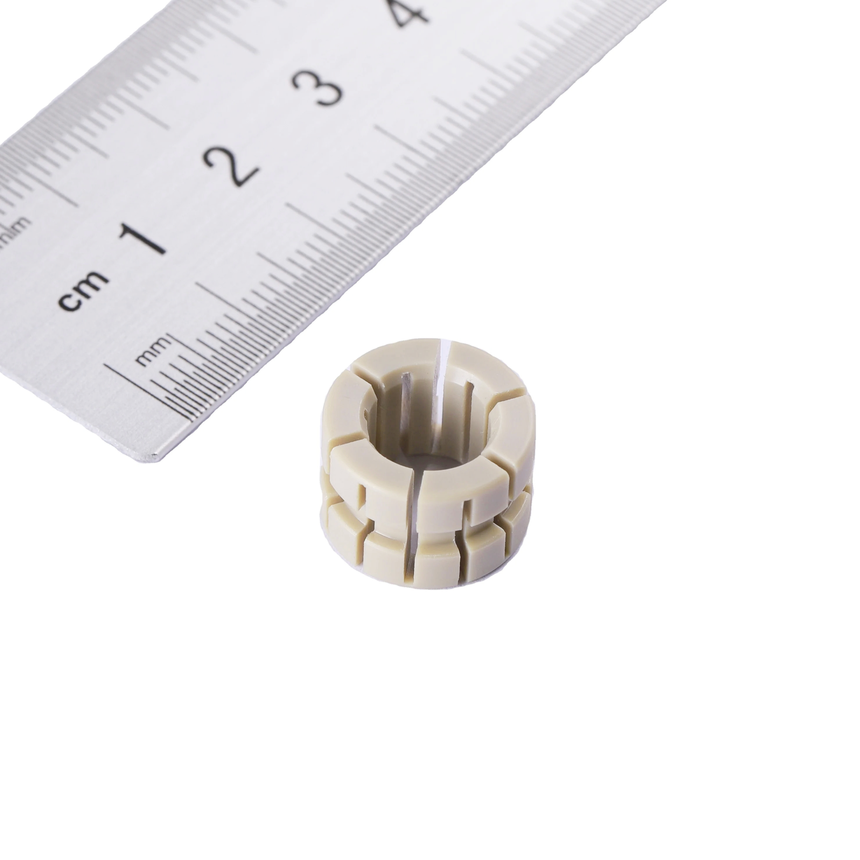
Miniature PEEK injection molded parts

2.Why choose unfilled grade?

2.1Virgin PEEK has higher flow than fiber filled grade

At the same Series of PEEK pellets,Unfilled grade has better fluidity of fiber reinforced grade.

For example:under the test standard ISO 1133,380°C,5kg load:

The ultra high flow unfilled PEEK(660G) Melt index can reach 80g/10min.

20% Glass fiber filled ultra high flow PEEK(PRESTM660GF20) Melt index can reach 40g/10min

20% Carbon fiber filled ultra high flow PEEK(PRESTM660CF20) Melt index can reach 31g/10min

30% Glass fiber filled ultra high flow  PEEK(PRESTM660GF30) Melt index can reach 28g/10min

30% Carbon fiber filled ultra high flow  PEEK(PRESTM660CF30) Melt index can reach 27g/10min

Fiber content Melt index Test standard
0% 80g/10min 1133,380°C,5kg load
20% Glass fiber 40g/10min 1133,380°C,5kg load
30% Glass fiber  28g/10min 1133,380°C,5kg load
20% Carbon fiber 31g/10min 1133,380°C,5kg load
30% Carbon fiber 27g/10min 1133,380°C,5kg load

From this table, it can be seen that the fluidity of PEEK material is not only affected by the fiber content, but also different types of fibers will influence the fluidity of PEEK material. For the same series of PEEK materials, the higher the fiber content, the fluidity is lower. 

In the same series, with the same fiber content, the fluidity of carbon fiber PEEK is lower than that of glass fiber PEEK.

2.2Unfilled grade PEEK is earier to fill the Mold cavity and reach higer precision.

The wall thickness of micro injection molded parts is usually quite small. Once the molten material comes into contact with the mold surface, it begins to cool down. For PEEK material with poor fluidity, the temperature drop at the end of the mold cavity causes the viscosity to rapidly increase and makes it impossible for the material to continue flowing. The highly mobile PEEK material can maintain good fluidity even as the melt temperature continuously decreases, and it can completely fill the mold before the material undergoes crystallization or solidification.

2.3Why is the ultra High flow PEEK material more suitable for high-precision components?

The ultra high flow PEEK can better fill the complex-shaped cavities, ensuring the geometric integrity of high-precision parts.

The PEEK components produced by high-flow molding have less internal stress. During the injection process, the molecules experience less stretching and lower orientation stress. Moreover, during the holding-pressure stage, a smaller holding-pressure force is required, further reducing the stress. By setting the mold temperature at a higher level of 170–190℃, the overall crystallinity and the consistency of crystallization are enhanced. As a result, the PEEK components have less deformation after production and are easier to complete the subsequent assembly work.

And because it contains no fibers, the material causes minimal wear to the gate, runner, and cavity, and even after long periods of production, it can still maintain excellent dimensional consistency.

3.When to choose high flow reinforced grade PEEK?

The high-flow fiber reinforced PEEK material is  ultra-high flow PEEK resin + glass fibers or carbon fibers. Fibers will reduce the fluidity of PEEK material, but the high-flow-enhanced grade PEEK still has higher fluidity. The reinforced material has a higher heat distortion temperature and mechanical strength compared to the unfilled PEEK material. The addition of glass fibers enhances the strength while still maintaining insulation, and the addition of carbon fibers can improve the wear resistance of the product.

As mentioned earlier, the content of fibers also affects the fluidity. When we need higher strength but the viscosity of the 30% fiber-reinforced material is too high, we can choose the high-flow PEEK with 20% fiber reinforcement.

4.How to injection ultra-high flow PEEK?

The injection molding of high-flow PEEK thin-wall parts (wall thickness <1mm, even 0.3–0.5mm) differs significantly from standard or high-viscosity PEEK. The challenge with standard-viscosity PEEK in thin-wall and micro parts is filling the mold; for high-flow or ultra-high-flow PEEK, the difficulty lies in avoiding burn marks, preventing flash, and minimizing warpage during high-speed filling.
Key considerations for molding high-flow PEEK:
  1. Mold venting: Prevent gas trap and burn. At high-speed thin-wall filling, trapped gas is more common than short shots. Parting line vent depth should be 0.015–0.03mm, width 3–10mm; vent inserts are mandatory at melt ends and weld lines.

  2. Clamping force: Low-viscosity high-flow PEEK has strong penetration and easily causes flash. Sufficient clamping force is required—estimate at projected area × 800–1000 bar.

  3. Melt temperature: High-flow grades can run at lower temperatures to avoid local degradation, but long-flow-path parts still need higher temperatures. The selection is based on L/t (flow length ratio) and fill time, not just wall thickness: thin-wall short flow (L/t <150) uses 365–375°C; standard thin-wall (L/t 150–200) uses 370–380°C; long flow path (L/t >200) requires 380–390°C to maintain front-end fluidity and prevent freeze-off.

  4. Mold temperature: Thin-wall PEEK cools rapidly and requires high mold temperature plus zoned control according to wall thickness variations to ensure higher crystallinity and better consistency.

4.1Drying

Although PEEK has low moisture absorption, thorough drying is essential—especially for precision molding where moisture content must be strictly controlled. Temperature should be uniformly set at 150–160°C (not lower than 150°C; this applies to high-flow virgin resin as well to prevent trace moisture from flashing into silver streaks under high shear). Duration: 3–6 h. Dew point: ≤-40°C dehumidified drying. Target moisture: ≤0.02%. If shutdown exceeds 30 min: re-dry for ≥2 h.

4.2Barrel Temperature

Standard PEEK typically uses 360–390°C. Ultra-high-flow PEEK has lower viscosity and does not need the upper range—high-flow grades usually run at 370–380°C, and thin-wall short-flow can drop to 365–375°C. Excessive temperature causes over-shearing; local temperatures >420°C can induce shear degradation and carbonization. When Flow Length Ratio (actual melt flow path length divided by corresponding section thickness, including runner length in production) is high (>200), a barrel temperature of 380–390°C is needed to ensure complete cavity fill at the flow front.

4.3Mold Temperature

PEEK thin-wall and micro parts cool quickly in the mold and require high mold temperature to ensure complete fill and high crystallinity, typically set at 180–200°C. Higher crystallinity gives PEEK better mechanical properties and chemical resistance.
Zoned temperature control is highly recommended, set by wall thickness: gate area 5–10°C higher than cavity (prevents gate freeze); flow end/thin ribs 5–10°C higher (delays front freeze-off); core (deep cavities) on a separate high-flow circuit (cores dissipate heat slowly); thick sections on a separate slightly lower circuit (prevents post-shrinkage).
Mold design should include thermocouple holes. Actual cavity temperature during production must be measured using mold insert thermocouple holes + Type K thermocouples in clamped (closed) condition. Measurements taken after mold opening only reflect residual temperature—air convection causes a 10–30°C drop within seconds and cannot represent working conditions. Infrared thermometers are only for auxiliary comparison after opening and cannot replace closed-mold thermocouple readings as acceptance criteria. Hole depth: 1–3mm from cavity surface; apply high-temp thermal paste and seat probe firmly at bottom. Preheat 30–60 min before reading; cavity-to-cavity variation should be ≤±2°C.
Important note: The oil unit panel shows heater outlet oil temperature. Oil travels through heater → hose → mold interface → water channel → mold steel → cavity surface, with heat loss at every stage. Panel temperature ≠ actual cavity temperature; deviation can reach 10–30°C.
4.4. Injection & Packing
Injection speed should be staged: gate zone (0–30%) at 30–50 mm/s to prevent jetting; main fill (30–90%) at 80–120 mm/s for high-speed cavity fill; tail (90–100%) at 20–40 mm/s to allow venting and prevent burn. Injection pressure: 120–180 MPa. Packing pressure: 30–50% of injection pressure. Packing time: 1–2 s per mm of wall thickness (0.5mm part ≈ 1–3s). Transfer to packing at 98% cavity fill.
4.5.Additional Mold Design Points
Gate size should be 30–50% larger than for ABS/PC; fan gate is preferred over pinpoint gate to avoid shear overheating. Runners should be round, diameter 5–8 mm, polished inner surface Ra≤0.4μm. Draft angle ≥1° (1.5° recommended for precision parts).
4.6Recommended Trial Run Sequence
  • Step 1: Dry at 150°C/4h; install thermocouples (lead out in clamped condition).

  • Step 2: Start oil unit 30–60 min before molding.

  • Step 3: Preheat in clamped condition; confirm cavity temp reaches 180–190°C via thermocouple before first shot.

  • Step 4: Disable packing; run short shots at 30% → 50% → 80% → 95% to map fill pattern.

  • Step 5: Once full, start packing at 30% injection pressure / 1s; increase gradually.

  • Step 6: After dimensional stability is confirmed, anneal: 200°C/2–4h, furnace cool.

4.7Defect Troubleshooting
Burn marks or silver streaks at end → Check venting first, not temperature. White or cold weld at end → Mold temp too low or front freeze-off. Flash at parting line → Insufficient clamping force or excessive packing. Warpage → Packing too long or mold temp uneven. Short shot → Check actual mold temp first, then speed/gate. Dimensional drift → Crystallinity variation; calibrate zoned temperature.


Rio Liang | High-Performance Plastics Expert
 
Email: rioplastic@foxmail.com   TEL/Whatsapp/Wechat: 008613421811533
 
20+ Years specializing in PEEK, PPSU, PES, PPS & PEI materil modification. Expert in resolving material properties and injection molding solutions. Open to technical discussions.

Related Articles

As a high-performance plastic supplier in China, PRES offers a range of high-performanceplastic products, including plastic pellets, plastic plates, plastic rods, plastic tubes, plastic powders, and high-performance 3D printing filaments.
Meanwhile, we provide mold design & manufacturing & injection molding services.

CONTACT US

Phone: +86 18676969309
Wechat:18676969309
Email: rioplastic@foxmail.com
WhatsApp: +86 18676969309
Add: No. 417, Chang Road, Changping Town, Dongguan City, Guangdong Province
KEEP IN TOUCH WITH US
Copyright © Dongguan PRES Plastic Raw Materials Co., Ltd. All Rights Reserved.