Views: 237 Author: Dongguan PRES Publish Time: 2026-09-28 Origin: Site


Content Menu
● Why PEEK Fillers Change Machinability
● Glass-Filled PEEK: Strength With High Abrasiveness
>> How glass fibers affect cutting tools
● Carbon-Filled PEEK: Higher Load Capacity, Different Trade-Offs
● Glass-Filled vs. Carbon-Filled PEEK
>> Best tool choices for filled PEEK
● Practical Machining Guidelines for Filled PEEK
>> 1. Begin with a stable, stress-relieved material
>> 2. Use conservative speed as a starting point
>> 3. Maintain a sharp cutting edge
>> 5. Match finishing operations to fiber behavior
● Expert Insight: Measure Cost Per Good Part
● When to Choose Glass-Filled PEEK
● When to Choose Carbon-Filled PEEK
● Request a Filled PEEK Material Consultation
● FAQ
>> Is glass-filled PEEK harder to machine than virgin PEEK?
>> Is carbon-filled PEEK more abrasive than glass-filled PEEK?
>> What cutting tools are best for glass-filled and carbon-filled PEEK?
>> Can standard carbide tooling machine PEEK GF30 or CF30?
>> Should filled PEEK be annealed before machining?
>> Does carbon-filled PEEK conduct electricity?
>> Which is better for wear components: glass-filled or carbon-filled PEEK?
At Dongguan PRES Group Co., Ltd., we help overseas brands, wholesalers, and manufacturers source and develop high-performance PEEK materials—from resin pellets and powders to sheets, rods, tubes, and high-performance 3D-printing filament. One of the most important questions we receive is: how do glass fiber and carbon fiber fillers affect PEEK machinability and tool wear?
The short answer is clear: both glass-filled PEEK and carbon-filled PEEK offer major gains in stiffness, dimensional stability, and load capacity, but both are substantially more demanding to machine than virgin PEEK. The fiber reinforcement that makes the finished part stronger also changes chip formation, cutting forces, surface finish, and—most importantly—cutting-tool life.
For CNC shops, OEMs, and product engineers, choosing between glass-filled PEEK vs. carbon-filled PEEK should never be based only on mechanical properties. It must also account for machining cost, tool selection, part geometry, thermal performance, surface requirements, electrical behavior, and production volume.

PEEK, or polyether ether ketone, is already a high-performance semi-crystalline engineering thermoplastic. It combines heat resistance, chemical resistance, low moisture uptake, mechanical strength, and excellent long-term reliability.
Virgin PEEK is comparatively easy to machine when the right process discipline is used. It can still generate heat, deform if poorly fixtured, or develop burrs if cutting edges become dull. However, its uniform polymer structure allows sharp carbide tools to produce clean chips and stable finishes.
Once reinforcement is added, the material becomes a composite.
Glass fibers or carbon fibers are dispersed in the PEEK matrix. During machining, the cutting edge must repeatedly shear polymer and fracture, cut, or pull out fibers. This creates a more abrasive cutting zone and a less predictable surface-generation process.
At PRES, we advise customers to treat filled PEEK not as "standard PEEK with extra strength," but as a distinct machining material class.
The main machining effects of fillers include:
- Faster flank wear on cutting edges.
- Micro-chipping of brittle or insufficiently supported tool edges.
- Higher cutting forces compared with virgin PEEK.
- More surface variability due to exposed, fractured, or pulled-out fibers.
- Greater dimensional risk when worn tools generate friction and heat.
- Different chip behavior, especially in drilling, slotting, and deep-pocket machining.
- Increased need for preventive tool replacement, rather than waiting for visible part defects.
Glass-filled PEEK usually contains approximately 10% to 30% glass fiber, with 30% glass-filled PEEK (PEEK GF30) being a common industrial grade. It is widely selected where stiffness, creep resistance, dimensional stability, electrical insulation, and thermal performance are more important than low-friction sliding behavior.
Glass-filled PEEK is often used in:
- Electrical insulation components.
- Semiconductor fixtures.
- Oil and gas parts.
- Aerospace structural components.
- Pump and valve elements.
- High-temperature jigs and fixtures.
- Precision machined components exposed to sustained static loads.
Glass fiber reinforcement improves stiffness and dimensional stability compared with unfilled PEEK. It is particularly useful for parts that must retain shape under elevated temperature and long-term mechanical loading. Ensinger notes that 30% glass-filled PEEK improves mechanical strength, rigidity, creep resistance, and dimensional stability, but can have an abrasive effect on mating surfaces.
In our experience supporting PEEK machining projects, glass-filled PEEK is often the more abrasive option at the cutting interface. Glass fibers are hard, brittle, and highly effective at dulling a conventional carbide edge.
The result is usually progressive abrasive wear:
1. The cutting edge loses sharpness.
2. Cutting friction rises.
3. Cutting temperature increases.
4. The polymer matrix may smear rather than shear cleanly.
5. Surface finish declines.
6. Burrs, dimensional drift, and fiber pull-out become more likely.
A dull tool can make a PEEK GF30 part look acceptable early in a machining cycle, then suddenly generate unacceptable features as the edge crosses a wear threshold. This is why a tool-change schedule is often more reliable than visual inspection alone.
Key machining takeaway: Glass-filled PEEK rewards sharp, wear-resistant tooling and disciplined tool-life management. It is not a suitable candidate for "run it until it fails" machining practices.
Carbon-filled PEEK commonly contains around 30% carbon fiber. PEEK CF30 is typically selected for parts needing high stiffness, improved compressive performance, lower thermal expansion, enhanced thermal conductivity, and demanding load-bearing capability.
Carbon-filled PEEK is frequently used for:
- High-load structural components.
- Aerospace and motorsport parts.
- Bearing-support structures.
- Compressor and pump components.
- Industrial automation elements.
- Precision fixtures requiring low thermal expansion.
- Weight-sensitive high-performance assemblies.
Compared with glass-filled PEEK, carbon-filled PEEK is generally lighter at an equivalent reinforcement level and is often selected where stiffness-to-weight ratio matters. Carbon fiber reinforcement can also improve heat transfer relative to virgin PEEK, which may help a component dissipate heat in service. For example, a 30% carbon-filled PEEK grade has been reported to offer about 3.5 times the thermal conductivity of unfilled PEEK.
However, carbon-filled PEEK is not automatically easier to machine.
Carbon fiber reinforcement creates a cutting environment where the tool alternates between shearing the PEEK matrix and severing stiff fibers. This can cause abrasive wear, edge rounding, localized chipping, and surface defects if the tool geometry or machining strategy is unsuitable.
Carbon-filled PEEK is commonly described as highly abrasive and is generally more difficult to machine than virgin PEEK. Depending on fiber architecture, filler loading, cutting conditions, and tool material, it can be at least as demanding as glass-filled PEEK.
There is an important nuance: glass fibers are often considered more abrasive to a cutting edge, while carbon-filled grades can create broader process challenges involving stiffness, fiber breakage, chip evacuation, conductivity, and surface integrity.
A 30% carbon-fiber-reinforced PEEK material is specifically designed for higher strength and stiffness, while glass- and carbon-fiber-reinforced PEEK grades are both used for demanding geometries and mechanical requirements.
For a machining engineer, this means the correct question is not simply, "Which filler is harder on tools?" The better question is:
Which material and process combination produces the lowest total cost per acceptable part?
That calculation must include raw material, machining time, tool cost, scrap rate, inspection burden, cycle stability, and end-use performance.
| Machining factor | Glass-filled PEEK | Carbon-filled PEEK | Practical implication |
|---|---|---|---|
| Typical reinforcement | Often 10–30% glass fiber | Often 10–30% carbon fiber | Confirm actual filler percentage before setting parameters |
| Tool abrasion | Very high; glass is highly abrasive | High; fiber cutting and edge wear remain significant | PCD tooling is strongly preferred for production |
| Stiffness | High | Usually higher | CF-PEEK can reduce deflection but may increase cutting force |
| Dimensional stability | Excellent | Excellent, often with lower thermal expansion | Both suit tight-tolerance work when stress is controlled |
| Thermal conductivity | Relatively low | Higher than unfilled and glass-filled grades | CF-PEEK may transfer cutting heat differently |
| Electrical behavior | Generally insulating | Electrically conductive or dissipative depending on grade | Material selection affects ESD and electrical-isolation requirements |
| Surface appearance | Natural/light gray and fiber-textured | Black and fiber-textured | Cosmetic requirements may influence grade selection |
| Wear-part suitability | Not usually preferred for sliding contact due to glass abrasiveness | Better potential in load-bearing and wear-focused formulations | Consider dedicated bearing-grade PEEK for moving contact surfaces |
| Recommended production tool | PCD or diamond-coated tooling | PCD or diamond-coated tooling | Carbide may be acceptable for prototypes, not ideal for long runs |
Important: Filler percentage, fiber length, fiber orientation, resin grade, extrusion history, annealing condition, part geometry, and coolant method can all alter actual results. Do not assume every GF30 or CF30 grade machines identically.
For virgin PEEK, polished micro-grain carbide tooling can often deliver reliable results. For glass-filled and carbon-filled PEEK, the tool strategy should change.
- PCD tools: Usually the preferred option for sustained production of glass-filled or carbon-filled PEEK.
- Diamond-coated carbide tools: A practical option where PCD tool geometry is unavailable or part geometry is complex.
- Fine-grain carbide tools: Suitable for prototypes, small batches, or non-critical operations, but expect faster wear.
- Sharp polished geometry: Helps lower friction, improve chip flow, and reduce matrix smearing.
- Positive rake angles: Can reduce cutting forces, though the exact geometry must match the operation and required edge strength.
Industry guidance consistently identifies PCD or diamond-based solutions as appropriate for reinforced PEEK because fibers accelerate wear on standard cutting tools.
A PCD tool is not a universal solution if the geometry is wrong.
For example:
- A tool with insufficient edge support may chip in interrupted cuts.
- A dull edge may heat the polymer matrix and create melted or smeared surfaces.
- A poor flute design can trap abrasive chips in deep cavities.
- An excessive nose radius can increase rubbing instead of clean shearing.
- An overly aggressive feed may tear fibers from the part surface.
At PRES, we encourage OEM customers to qualify material, tool geometry, and finishing requirements as one integrated process—not as separate purchasing decisions.
Machining parameters must be validated through trials, but the following principles create a strong starting point for glass-filled and carbon-filled PEEK.
For tight-tolerance parts, use properly conditioned stock and consider annealing before final machining. Internal stress can lead to movement after material removal, especially in thick sections, asymmetric geometries, thin walls, and close-tolerance parts.
Annealing is especially valuable when:
- Tolerances are tight.
- The component has deep pockets.
- The part is thin-walled.
- Significant material is removed from one side.
- The component will face high service temperatures.
- Long-term dimensional stability is critical.
Filled PEEK generally requires more conservative cutting conditions than virgin PEEK. One published processing guide for reinforced PEEK lists turning speeds in the range of 120–180 m/min, compared with 300 m/min for unreinforced material.
That does not mean every operation should use the same number. Milling, drilling, turning, tool diameter, coolant supply, machine rigidity, and specific grade all matter. The key is to avoid the false economy of excessive speed, which can rapidly accelerate wear and compromise finish.
A sharp edge lowers friction and reduces the chance of pushing, rubbing, or smearing the polymer matrix. Replace tools before the edge becomes visibly rounded enough to create burrs, heat marks, poor finishes, or dimensional variation.
Monitor:
- Flank wear.
- Edge chipping.
- Surface roughness trends.
- Burr formation.
- Hole-size drift.
- Cutting-force changes.
- Spindle-load trends.
- Heat discoloration or matrix smearing.
Filled PEEK machining produces abrasive chips. These chips should not be allowed to recirculate through the cutting zone.
Use:
- Effective chip evacuation.
- Targeted compressed air where appropriate.
- Flood coolant when compatible with the component, machine, and downstream cleanliness requirements.
- Vacuum extraction for fine particulate control.
- Clean workholding and clean fixtures.
For drilling, especially deep holes, use a controlled peck cycle and ensure chips clear efficiently. Poor evacuation can cause localized overheating, hole-surface damage, and premature tool wear.
A high-quality finish in fiber-filled PEEK requires realistic expectations. Fiber ends may be exposed at the machined surface, especially when the cutter intersects fibers unfavorably.
To improve surface integrity:
- Use a dedicated finishing pass.
- Avoid running a worn roughing tool into a final pass.
- Reduce radial engagement during finishing.
- Maintain stable fixturing.
- Select a tool path that minimizes repeated rubbing.
- Test climb versus conventional milling for the specific geometry.
- Inspect critical sealing, bearing, or cosmetic surfaces under magnification.
The most common purchasing mistake is comparing only the price per kilogram of GF30 PEEK and CF30 PEEK. The most useful metric is cost per good part.
For example, a lower-cost material may become more expensive if it causes:
- Frequent tool changes.
- Longer finishing operations.
- High burr-removal labor.
- Poor hole quality.
- Tool-related scrap.
- Unstable tolerances.
- Delays in production qualification.
Conversely, a premium carbon-filled PEEK grade may justify its cost when it provides stiffness, reduced thermal expansion, or load capacity that allows the customer to redesign the part, reduce weight, eliminate metal inserts, or extend service life.
At Dongguan PRES Group Co., Ltd., we work from this application-first perspective. As a China-based manufacturer and OEM partner for high-performance plastic products, we support customers not only with PEEK pellets, sheets, rods, tubes, powders, and 3D-printing filament, but also with material-format selection and application-focused technical communication.
Choose glass-filled PEEK when the application prioritizes:
- Electrical insulation.
- High rigidity.
- Good creep resistance.
- Dimensional stability at elevated temperature.
- Chemical resistance.
- Static-load performance.
- High-temperature industrial fixtures.
- A cost-conscious reinforced PEEK solution.
Be cautious if the component will run against a sensitive mating surface. Glass fibers can be abrasive in service as well as during machining. Ensinger specifically notes that glass-filled PEEK is less suitable for bearing and wear applications because glass fibers can have a marked abrasive effect on mating surfaces.
Choose carbon-filled PEEK when the application prioritizes:
- High stiffness-to-weight ratio.
- Improved compressive and load-bearing performance.
- Lower thermal expansion.
- Better thermal conductivity than virgin PEEK.
- High-performance structural parts.
- Weight-sensitive aerospace or industrial components.
- Components where electrical conductivity or dissipation is acceptable or desired.
Be cautious when electrical insulation is mandatory. Carbon fiber reinforcement can change the electrical behavior of the part and may make carbon-filled PEEK unsuitable for insulating applications.
Dongguan PRES Group Co., Ltd. provides OEM-oriented support for international brands, wholesalers, and manufacturers that need dependable high-performance plastic material solutions.
Our PEEK product portfolio can include:
- PEEK pellets and compounds for molding and extrusion.
- PEEK sheets for CNC-machined plates, fixtures, and insulation components.
- PEEK rods for turned components, seals, bushings, and precision parts.
- PEEK tubes for demanding fluid, electrical, and industrial applications.
- PEEK powders for specialized processing needs.
- High-performance PEEK 3D-printing filament for advanced additive manufacturing projects.
- Customized OEM material solutions based on grade, filler type, geometry, color, packaging, and application requirements.
The right material decision starts before machining. A qualified supplier should help you define the correct PEEK formulation, product form, filler system, and quality expectations before the first CNC program is released.
If you are sourcing glass-filled PEEK, carbon-filled PEEK, PEEK sheets, rods, tubes, pellets, powders, or high-performance 3D-printing filament, contact Dongguan PRES Group Co., Ltd. with your drawing, application environment, annual volume, target properties, and machining requirements.
Our team can help you compare PEEK GF30 vs. PEEK CF30, select a suitable material form, and develop an OEM supply approach that supports both part performance and manufacturing efficiency.
Yes. Glass-filled PEEK is significantly more abrasive than virgin PEEK because the tool must cut both the PEEK matrix and hard glass fibers. Tool wear is faster, surface finish is more difficult to control, and PCD or diamond-coated tooling is generally preferred for production.
Both materials are abrasive and require robust tooling. Glass fiber is often more aggressive in direct abrasive wear, while carbon-filled PEEK can still be highly challenging because of its high stiffness, fiber breakage behavior, cutting-force demands, and surface-finish requirements. The actual result depends on filler loading, fiber orientation, machining operation, and tool material.
PCD tools are usually the best choice for sustained production machining of filled PEEK. Diamond-coated carbide is also a practical option. Fine-grain carbide can be used for prototypes or short runs, but wear should be closely monitored.
Yes, standard carbide can machine these materials, especially for prototype work and low-volume jobs. However, its edge will wear more quickly than in virgin PEEK. For stable production, close tolerances, or large quantities, PCD or diamond-coated tooling is normally more economical over the full production cycle.
Annealing is recommended when the part has tight tolerances, thick sections, thin walls, deep pockets, large material removal, or high-temperature service requirements. It can reduce internal stress and improve dimensional stability after machining.
Carbon-filled PEEK can be electrically conductive or dissipative depending on its exact formulation and carbon-fiber content. It should not automatically be used where electrical insulation is required. Always confirm electrical properties with the specific material data sheet and application requirements.
Carbon-filled PEEK is generally more suitable than glass-filled PEEK for high-load and wear-related applications, although a dedicated bearing-grade PEEK containing PTFE, graphite, and carbon fiber may be the best choice for sliding or friction-critical components. Glass-filled PEEK is often less suitable where the mating surface may be damaged by exposed glass fibers. 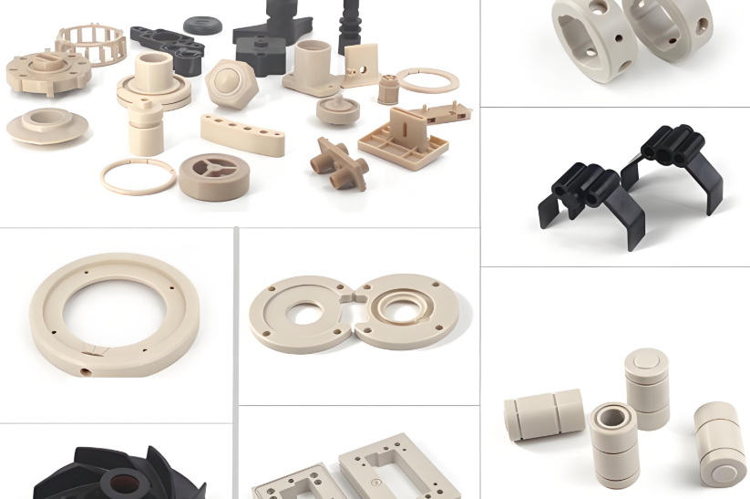
1. Victrex. "VICTREX™ PEEK Polymers: Materials for Demanding Applications." [View source].
2. Victrex. "VICTREX™ PEEK Polymer 450CA30 Datasheet." [View source].
3. Ensinger. "TECAPEEK GF30 Natural: Glass Fiber Reinforced PEEK." [View source].
4. EMCO Plastics. "Processing Guide: VICTREX PEEK." [View source].
5. Drake Plastics. "PEEK Polymer Guide." [View source].
6. PTSMAKE. "The Ultimate Guide to PEEK Machining Techniques." [View source].
7. PEEKCHINA. "What Is PEEK Machining?" [View source].
8. PEEKCHINA. "CF30 PEEK or GF30 PEEK?" [View source].
9. TiRapid. "PEEK CNC Machining Explained." [View source].
10. Criterion Precision. "PEEK Machining Guide: Properties, Tolerances and Medical Applications." [View source].
Hot Tags: China, Global, OEM, private label, manufacturers, factory, suppliers, manufacturing company